Item
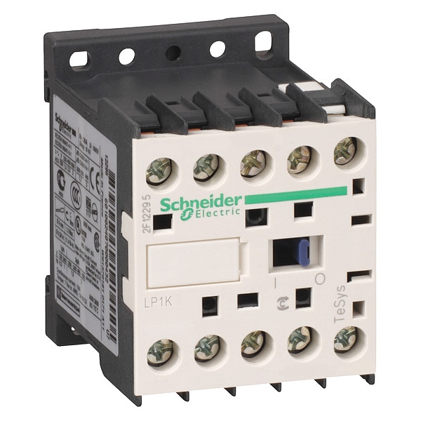
IEC Magnetic Contactor
Auxiliary Contact Form
No Auxiliary Contacts
Full Load Amps-Inductive
9 A
Full Load Amps-Resistive
20 A
Reversing Capability
Non-Reversing
Terminal Connection Type
Screw Clamp
Number of Auxillary Contacts
1
Standards
CSA, UKCA, UL Listed
Frame / Series / Class / Code
TeSys
Aux. Contact Configuration
None
Enclosure NEMA Rating
No Enclosure
Tightening Torque
0.8 to 1.3 Nm
Features
Built-In Bi-Directional Peak Limiting Diode Suppressor
Rated Breaking Capacity
110 A @ 415V, 440V, 220 to 230V, 380 to 400 V; 80 A @ 500V; 70 A @ 660 to 690V
Rated Making Capacity
110 A
Mechanical Durability
10 Mcycles
Application
Motor Control, Resistive Load
Switching Voltage
17 V (Signalling Circuit)
Fire Rating
UL 94 V1, NF F 16-101, NF F 16-102
Operating Speed
3600 cycles per hr
Fuse Amps
25 A (Power Circuit), 10 A (Signalling Circuit)
Impulse Withstand Voltage
8 kV
Control Circuit Voltage Limits
Operational: 0.8 to 1.15 Uc (at 50°C), Drop-Out: 0.1 to 0.75 Uc (at 50°C)
Rated Insulation Volts
600/690V
Overvoltage Category
CAT III
Operating Time
30 to 40 ms (Coil Energisation and NO Closing), 10 ms (Coil De-Energisation and NO Opening)
Environmental Attributes
Mercury Free, Toxic Heavy Metal Free
Thermal Amperage
20 A (at 50°C Power Circuit), 10 A (at 50°C Signalling Circuit)
Switching Current
5 mA (Signalling Circuit)
Electrical Durability
1.3 Mcycles 9 A AC-3 Less than or Equal to 440 V; 1.3 Mcycles 9 A AC-3e Less than or Equal to 440 V; 0.16 Mcycles 20 A AC-1 Less than or Equal to 690 V; 0.02 Mcycles 54 A AC-4 Less than or Equal to 440 V
Insulation Resistance Range
Greater Than 10 MOhms (Signalling Circuit)
Maximum Voltage Rating
690V AC
Minimum Operating Temperature
-13 Degrees F
Number of Normally Open Main Contacts
3
Includes Auxiliary Contacts
Yes
NEMA Enclosure Rating
No Enclosure
Maximum Operating Temperature
122 Degrees F
Mounting Style
DIN Rail, Plate
Full Load Current - Inductive
9 A
Resistance Properties
Insulation Resistant
Embedded Surge Suppressor
Yes
Full Load Current - Resistive
20 A
Mechanical Operating Durability
10,000,000
Rated Operational Voltage
Power circuit Less than or Equal to 690 V AC Less than or Equal to 400 Hz; Signalling circuit Less than or Equal to 690 V AC Less than or Equal to 400 Hz
Contactor Application
Resistive load; Motor control
Utilisation Category
AC-3; AC-3e; AC-1; AC-4
Conventional Free Air Thermal Current
20 A (at 140°F (60°C)) for power circuit; 10 A (at 122°F (50°C)) for signalling circuit
Ambient Air Temperature For Storage
-58 to 176°F (-50 to 80°C)
Inrush Power in W
3 W 68°F (20°C))
Maximum Operating Rate
3600 cyc/h
Associated Fuse Rating
25 A gG at Less than or Equal to 440 V for power circuit; 25 A aM for power circuit; 10 A gG for signalling circuit conforming to IEC 60947; 10 A gG for signalling circuit conforming to VDE 0660
Average Impedance
3 mOhm - Ith 20 A 50 Hz for power circuit
Rated Operational Current
9 A (at Less than 140°F (60°C)) at Less than or Equal to 440 V AC AC-3 for power circuit; 9 A (at Less than 140°F (60°C)) at Less than or Equal to 440 V AC AC-3e for power circuit; 20 A (at Less than 140°F (60°C)) at Less than or Equal to 690 V AC AC-1 for power circuit
Minimum Switching Current
5 mA for signalling circuit
Power Pole Contact Composition
3 NO
Connections - Terminals
screw clamp terminals 1 0.00 to 0.01 in² (1.5 to 4 mm²)solid; screw clamp terminals 1 0.00 to 0.01 in² (0.75 to 4 mm²)flexible without cable end; screw clamp terminals 1 0.00 to 0.00 in² (0.34 to 2.5 mm²)flexible with cable end; screw clamp terminals 2 0.00 to 0.01 in² (1.5 to 4 mm²)solid; screw clamp terminals 2 0.00 to 0.01 in² (0.75 to 4 mm²)flexible without cable end; screw clamp terminals 2 0.00 to 0.00 in² (0.34 to 1.5 mm²)flexible with cable end; Power circuit screw clamp terminals 2 0.00 in² (1.5 mm²)flexible with cable end
Operating Altitude
6561.68 ft (2000 m) without derating
Rated Insulation Voltage
Power circuit 600 V UL 508; Power circuit 690 V IEC 60947-4-1; Signalling circuit 690 V IEC 60947-4-1; Signalling circuit 690 V IEC 60947-5-1; Signalling circuit 600 V UL 508; Power circuit 600 V CSA C22.2 No 14; Signalling circuit 600 V CSA C22.2 No 14
Coil Technology
Built-in bidirectional peak limiting diode suppressor
Ambient Air Temperature For Operation
-13 to 122°F (-25 to 50°C)
Safety Reliability Level
B10d = 1369863 cycles contactor with nominal load EN/ISO 13849-1; B10d = 20000000 cycles contactor with mechanical load EN/ISO 13849-1
Motor Power KW
2.2 kW 220 to 230 V AC 50/60 Hz AC-3; 4 kW 380 to 415 V AC 50/60 Hz AC-3; 4 kW 440/690 V AC 50/60 Hz AC-3; 2.2 kW 220 to 230 V AC 50/60 Hz AC-3e; 4 kW 380 to 415 V AC 50/60 Hz AC-3e; 4 kW 440/690 V AC 50/60 Hz AC-3e; 2.2 kW 220 to 230 V AC 50/60 Hz AC-4; 4 kW 380 to 415 V AC 50/60 Hz AC-4; 4 kW 440/690 V AC 50/60 Hz AC-4
Rated Short Time Withstand Current
90 A 122°F (50°C) - 1 s for power circuit; 85 A 122°F (50°C) - 5 s for power circuit; 80 A 122°F (50°C) - 10 s for power circuit; 60 A 122°F (50°C) - 30 s for power circuit; 45 A 122°F (50°C) - 1 min for power circuit; 40 A 122°F (50°C) - 3 min for power circuit; 20 A 122°F (50°C) - Greater than or Equal to 15 min for power circuit; 80 A - 1 s for signalling circuit; 90 A - 500 ms for signalling circuit; 110 A - 100 ms for signalling circuit
Auxiliary Contacts Type
Instantaneous 1 NO
Control Circuit Type
DC standard
IP Degree Of Protection
IP2X
Product Certifications
CB Scheme; CCC; UL; CSA; EAC; CE; UKCA
Insulation Resistance
Greater than 10 MOhm for signalling circuit
Minimum Switching Voltage
17 V for signalling circuit
Mounting Support
Plate; Rail
Flame Retardance
V1 conforming to UL 94; Requirement 2 conforming to NF F 16-101; Requirement 2 conforming to NF F 16-102
Hold-In Power Consumption in W
3 W 68°F (20°C)
Product Or Component Type
Contactor
IRMS Rated Making Capacity
110 A AC for power circuit conforming to IEC 60947; 110 A AC for signalling circuit conforming to IEC 60947