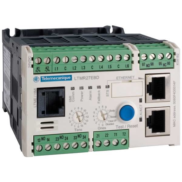
electrostatic discharge, 3, 8 kV air, 6 kV contact, conforming to EN/IEC 61000-4-2 || communication: surges (common mode), 2 kV, conforming to EN/IEC 61000-4-5 || relay outputs and supply: surges (serial mode), 2 kV, conforming to EN/IEC 61000-4-5 || relay outputs and supply: surges (common mode), 4 kV, conforming to EN/IEC 61000-4-5 || control circuit: surges (common mode), 2 kV, conforming to EN/IEC 61000-4-5 || radiated RF fields, 3, 10 V/m, conforming to EN/IEC 61000-4-3 || fast transients immunity test (other circuits), level 3, 2 kV, conforming to EN/IEC 61000-4-4 || fast transients immunity test (on supply and relay outputs), level 4, 4 kV, conforming to EN/IEC 61000-4-4 || voltage dips and interruptions immunity test, 70 %, 500 ms, conforming to EN/IEC 61000-4-11 || conducted RF disturbances, 10 V, conforming to EN/IEC 61000-4-6 || temperature sensor: surges (serial mode), 0.5 kV, conforming to EN/IEC 61000-4-5 || temperature sensor: surges (common mode), 1 kV, conforming to EN/IEC 61000-4-5 || control circuit: surges (serial mode), 1 kV, conforming to EN/IEC 61000-4-5
Fire Resistance
650°C EN/IEC 60695-2-12 || 960°C UL 94
Operating Altitude
<= 6561.68 ft (2000 m) without derating
Bus Type
Ethernet IEEE 802.3 0 to 159 10 to 100 Mbit/s, RJ45 2 shielded twisted pairs
Pollution Degree
3
Associated Fuse Rating
4 A gG output || 0.5 A gG control circuit
Current State 1 Guaranteed
logic input 79 to 264 V >= 2 mA 25 ms
Protective Treatment
12 x 24 hour cycles EN/IEC 60068-2-30 || 48 h EN/IEC 60070-2-11 || TH EN/IEC 60068
Device Short Name
LTMR
Ambient Air Temperature For Storage
-40-80°C
Short-Circuit Withstand
100 kA conforming to EN/IEC 60947-4-1
Permissible Power
480 VA AC-15), Ie = 2 A, 500000 cycles output) || 30 W DC-13), Ie = 1.25 A, 500000 cycles output)
Current State 0 Guaranteed
logic input 0 to 40 V <= 15 mA 25 ms
Compatibility Code
LTMR
Measurement Current
0.4-8 A
Contacts Type And Composition
1 NO + 1 NC fault signal || 3 NO
Network And Machine Diagnosis Type
trip context information || phase fault and earth fault trip counters || trip history information || event recording || remaining operating time before overload tripping || starting current and time || fault recording || waiting time after overload tripping || running hours counter/operating time || motor control command recording
Load Current
5 A 250 V AC logic output || 5 A 30 V DC logic output
[Uimp] Rated Impulse Withstand Voltage
4 kV supply, inputs and outputs EN/IEC 60947-4-1 || 6 kV current or voltage measurement circuit EN/IEC 60947-4-1 || 0.8 kV communication circuit EN/IEC 60947-4-1
vibrations mounted on symmetrical rail1 Gn, 5 to 300 Hz EN/IEC 60068-2-6 || vibrations plate mounted4 Gn, 5 to 300 Hz EN/IEC 60068-2-6 || shocks half sine wave acceleration15 Gn for 11 ms EN/IEC 60068-2-27
Measurement Accuracy
5 to 15 % earth fault current internal measurement || 1 % voltage 100 to 830 V) || 3 % power factor || 5 % earth fault current external measurement || +/- 30 min/year internal clock || 0,02 Temperature || 1 % current || 5 % active and reactive power
[Ui] Rated Insulation Voltage
690 V EN/IEC 60947-1 || 690 V CSA C22.2 No 14 || 690 V UL 508
[Us] Rated Supply Voltage
100 to 240 V AC 50/60 Hz
Connection Pitch
5.08 mm
Ambient Air Temperature For Operation
-20-60°C
Communication Port Protocol
Modbus TCP/EtherNet/IP
Overvoltage Category
III
Logic Input Number
6
Web Services
web server
Connections - Terminals
control circuit connector 1 0.25-2.5 mm² AWG 24 to AWG 14)flexible with cable end || control circuit connector 1 0.2-2.5 mm² AWG 24 to AWG 14)flexible without cable end || control circuit connector 1 0.25-2.5 mm² AWG 24 to AWG 14)flexible without cable end || control circuit connector 1 0.2-2.5 mm² AWG 24 to AWG 14)solid without cable end || control circuit connector 2 0.2-1 mm² AWG 24 to AWG 14)flexible with cable end || control circuit connector 2 0.2-1.5 mm² AWG 24 to AWG 14)flexible without cable end || control circuit connector 2 0.5-1.5 mm² AWG 24 to AWG 14)flexible without cable end || control circuit connector 2 0.2-1 mm² AWG 24 to AWG 14)solid without cable end
Metering Type
earth-fault current || imbalance current || temperature || average current Iavg || phase current I1, I2, I3 RMS
Product Name
TeSys T
Ip Degree Of Protection
IP20
Number of Contacts Included
5
Minimum Current Rating
0.4 A
Compatible with Series
TeSys T
Number of Normally Closed Contacts
1
Number of Normally Open Contacts
4
Maximum Current Rating
8 A
Description
Motor Management System, Number of Normally Open Contacts 4, Number of Normally Closed Contacts 1, Number of Contacts Included 5, Operating Voltage 690V AC, Control Voltage 100-240V AC, Interface Ethernet/IP, Modbus/TCP, Compatible with Series TeSys T, Overall Width 3.58 in, Standards CSA C22.2 No 14, EN 60947-4-1, IACSE10, IEC 60947-4-1, nABS, nATEX, nBV, nC-tick, nCCC, nCSA, nDNV, nEAC, nGL, nKERI, nLROS, NOM, nRINA, nRMRoS, nUL, UL 508, Overall Height 2.4 in, Overall Depth 4.82 in