Delay Function
Pulse Signal
Number of Delay Functions
1
Minimum Time Setting
0.1 sec
Maximum Time Setting
100 hr
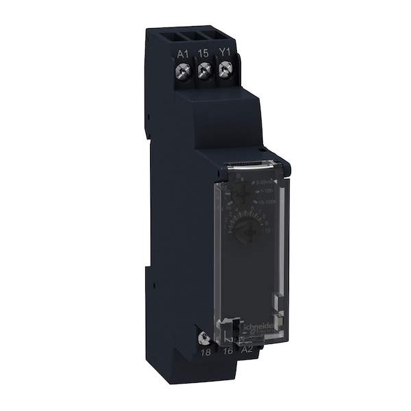
Adjustment Method - Timer
selector switch front panel
Electrical Connection
35 mm DIN rail conforming to EN/IEC 60715
Contact Material
cadmium free
Power Consumption - Relay
0-32 VA 240 V AC; 0.6 W 24 V DC
Input or Control Voltage Range
0.85...1.1 Us
Minimum Switching Current
10 mA 5 V DC
[Us] Rated Supply Voltage
24...240 V AC 50/60 Hz, 24 V DC
Range of Product
Harmony Timer Relays
Relative Humidity
93-93 % without condensation IEC 60068-2-30
Ambient Air Temperature For Operation
-20-60°C
Maximum Switching Voltage
250 V AC
Mounting Support
35 mm DIN rail conforming to IEC 60715
Mechanical Durability
10000000 cycles
Tightening Torque
0.6-1 N.m IEC 60947-1
Ip Degree of Protection
IP20 IEC 60529 terminal block), IP40 IEC 60529 housing), IP50 IEC 60529 front panel)
Ambient Air Temperature For Storage
-30-60°C
Shock Resistance
15 gn 11 ms IEC 60068-2-27
Immunity To Microbreaks
20 ms
Maximum Delay Response
100 ms
Vibration Resistance
20 m/s² 10-150 Hz)IEC 60068-2-6
Breaking Capacity
2000 VA
Operating Rate In Hz
10 Hz
Temperature Drift
+/- 0.05 %/°C
Electrical Durability
100000 cycles resistive 8 A 250 V AC
Voltage Drift
+/- 0.2 %/V
Impulse Duration
100 ms with load in parallel typical, 30 ms typical
Insulation Resistance
100 MOhm 500 V DC IEC 60664-1
Maximum Switching Current
8 A AC/DC
[Uimp] Rated Impulse Withstand Voltage
5 kV 1.2/50µs
Dielectric Strength
2.5 kV 1 mA/1 minute 50 Hz IEC 61812-1
Repeat Accuracy
+/- 0.5 % IEC 61812-1
Housing Material
self-extinguishing
Setting Accuracy of Time Delay
+/- 10 % of full scale 25°C IEC 61812-1
Mounting Position
any position in relation to normal vertical mounting plane
Reset Time
120 ms on de-energisation typical
Connections - Terminals
screw terminals, 1 x 0.5...1 x 3.3 mm² AWG 20...AWG 12) solid without cable end, screw terminals, 2 x 0.5...2 x 2.5 mm² AWG 20...AWG 14) solid without cable end, screw terminals, 1 x 0.2...1 x 2.5 mm² AWG 24...AWG 14) flexible with cable end, screw terminals, 2 x 0.2...2 x 1.5 mm² AWG 24...AWG 16) flexible with cable end
Creepage Distance
4 kV/3 IEC 60664-1
Nominal Output Current
8A
Supply Frequency
50...60 Hz +/- 5 %
Local Signalling
LED indicator on steady: relay energised, no timing in progress, LED indicator 80 % ON and 20 % OFF flashing: timing in progress, LED indicator 5 % ON and 95 % OFF pulsing: relay de-energised, no timing in progress (except function Di-D, Li-L)
Maximum Power Consumption In W
0.6 W 24 V DC
Electromagnetic Compatibility
electrostatic discharge immunity test 6 kV in contact) level 3 IEC 61000-4-2, electrostatic discharge immunity test 8 kV in air) level 3 IEC 61000-4-2, susceptibility to electromagnetic fields 10 V/m 80 MHz to 1 GHz) level 3 IEC 61000-4-3, electrical fast transient/burst immunity test 1 kV capacitive connecting clip) level 3 IEC 61000-4-4, electrical fast transient/burst immunity test 2 kV direct) level 3 IEC 61000-4-4, 1.2/50µs shock waves immunity test 1 kV differential mode) level 3 IEC 61000-4-5, 1.2/50µs shock waves immunity test 2 kV common mode) level 3 IEC 61000-4-5, conducted RF disturbances 10 V 0.15...80 MHz) level 3 IEC 61000-4-6, voltage dips and interruptions immunity test 0 % 1 cycle) IEC 61000-4-11, voltage dips and interruptions immunity test 70 % 25/30 cycles) IEC 61000-4-11, conducted and radiated emissionsclass B EN 55022