Item
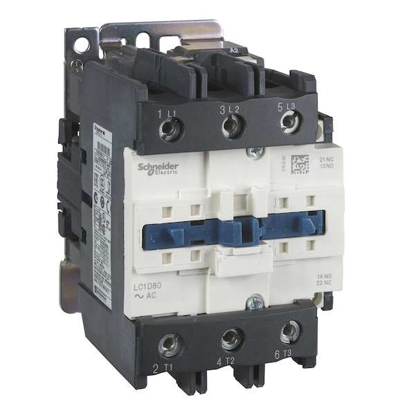
IEC Magnetic Contactor
Auxiliary Contact Form
1NC/1NO
Full Load Amps-Inductive
50 A
Full Load Amps-Resistive
80 A
Terminal Connection Type
Screw Clamp
Number of Auxillary Contacts
2
Standards
CSA C22.2 No 14, UL 508, IEC 60947-4-1, IEC 60947-5-1, EN 60947-5-1, EN 60947-4-1
HP @ 3 Phase - 575V
40 hp
Features
Without Built-In Bi-Directional Peak Limiting Diode Suppressor
Application
Motor Control, Resistive Load
Power Dissipation Per Pole
3.7 W AC-3, 9.6 W AC-1, 3.7 W AC-3e
Maximum Operating Rate
3600 cyc/h 60°C
Contactor Application
resistive load, motor control
Climatic Withstand
IACS E10 exposure to damp heat
Pole Contact Composition
3 NO
Operating Time
4...19 ms opening, 12...26 ms closing
Mechanical Robustness
shocks contactor opened 10 Gn for 11 ms) , shocks contactor closed 15 Gn for 11 ms) , vibrations contactor opened 2 Gn, 5...300 Hz) , vibrations contactor closed 4 Gn, 5...300 Hz)
Control Circuit Voltage Limits
0.3...0.6 Uc -40-70°C drop-out AC 50/60 Hz, 0.8...1.1 Uc -40-60°C operational AC 50 Hz, 0.85...1.1 Uc -40-60°C operational AC 60 Hz, 1...1.1 Uc 60-70°C operational AC 50/60 Hz
Utilisation Category
AC-3, AC-2, AC-1, AC-4, AC-3e
Control Circuit Type
AC 50/60 Hz
Tightening Torque
control circuit 1.7 N.m screw clamp terminal flat Ø 6 mm, control circuit 1.7 N.m screw clamp terminal Philips No 2, power circuit 5 N.m screw terminal flat Ø 6 to Ø 8 mm, control circuit 1.7 N.m screw clamp terminal pozidriv No 2
Operating Altitude
0...9842.52 ft (0...3000 m)
Auxiliary Contacts Type
mechanically linked 1 NO + 1 NC IEC 60947-5-1, mirror contact 1 NC IEC 60947-4-1
Non-Overlap Time
1.5 ms on de-energisation between NC and NO contacts, 1.5 ms on energisation between NC and NO contacts
Mechanical Durability
6000000 cycles
Heat Dissipation
4-5 W at 50/60 Hz for control circuit
Terminals Description Iso N°1
(A1-A2)CO, (13-14)NO, (21-22)NC
Fire Resistance
850°C IEC 60695-2-1
Rated Breaking Capacity
900 A at 440 V for power circuit conforming to IEC 60947
[Ui] Rated Insulation Voltage
control circuit 600 V CSA, control circuit 600 V UL, power circuit 600 V CSA, power circuit 600 V UL, control circuit 690 V IEC 60947-1, power circuit 690 V IEC 60947-1
Impulse Withstand Voltage
8 kV
Inrush VA
140 VA (at 20°C), 160 VA (at 20°C)
Hold VA
13 VA (at 60 Hz 20°C), 15 VA (at 50 Hz 20°C)
Fuse Amps
10 A (Control Circuit), 100 A (Type 1 and 2 Power Circuit)
Shock Resistance
15 G for 11 ms (Contactor Closed), 10 G for 11 ms (Contactor Open)
Switching Voltage
17 V (Control Circuit)
Operating Speed
3600 cycles per hr
Environmental Attributes
Mercury Free, PVC Free, Toxic Heavy Metal Free
Switching Current
5 mA (Control Circuit)
Insulation Resistance Range
Greater Than 10 Mohms (Control Circuit)
Max. Operating Watts
22 kW (at 380 to 400V AC 50 Hz), 25 kW (at 415V AC 50 Hz), 30 kW (at 440V AC 50 Hz), 30 kW (at 500V AC 50 Hz), 33 kW (at 660 to 690V AC 50 Hz), 15 kW (at 220 to 230V AC 50 Hz), 30 kW (at 1000V AC 50 Hz)
Includes Protective Cover
Yes
Vibration Resistance
4 G (Contactor Closed), 2 G (Contactor Open)
Rated Making Capacity
900 A @ 440V (Power Circuit), 140 A (AC Control Circuit)
Rated Insulation Volts
600/690V
Horsepower @ Single Phase - 240V AC
7 1/2 hp
Horsepower @ Three Phase - 480V AC
40 hp
Full Load Current - Inductive
50 A
Full Load Current - Resistive
80 A
Horsepower @ Three Phase - 240V AC
15 hp
Horsepower @ Three Phase - 208V AC
15 hp
Inrush Power in VA
140-140 VA cos phi 0.75 (at 20°C), 160-160 VA cos phi 0.75 (at 20°C)
Conventional Free Air Thermal Current
10 A (at 60°C Control Circuit), 80 A (at 60°C Power Circuit)
Rated Operational Current
50 A (at <60°C) at <= 440 V AC AC-3 for power circuit, 80 A (at <60°C) at <= 440 V AC AC-1 for power circuit, 50 A (at <60°C) at <= 440 V AC AC-3e for power circuit
Mounting Style
Plate, Rail
Control Circuit Voltage
208 V AC 50/60 Hz
Rated Operational Voltage
power circuit <= 690 V AC 25...400 Hz
Maximum Voltage Rating
690V AC