Item
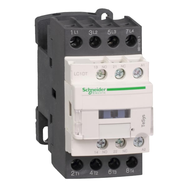
IEC Magnetic Contactor
Auxiliary Contact Form
1NC/1NO
Full Load Amps-Inductive
40 A
Full Load Amps-Resistive
40 A
Reversing Capability
Non-Reversing
Terminal Connection Type
Screw Clamp
Number of Auxillary Contacts
2
Standards
CSA C22.2 No 14, EN 60947-4-1, EN 60947-5-1, IEC 60947-4-1, IEC 60947-5-1, UL 508, IEC 60335-1, GL, CCC, LROS, BV, UL, RINA, CSA, GOST, DNV, THIEC 60068-2-30
Features
Without Built-In Suppressor Module
Application
Resistive Load
Fuse Amps
10 A (Signalling Circuit), 63 A (Type 1 Power Circuit), 40 A (Type 2 Power Circuit)
Electrical Durability
1.4 Mcycles (40 A, AC-1, Less than 440 V)
Insulation Resistance Range
Greater Than 10 MOhms (Signalling Circuit)
Electrical Connection
Screw Clamp Terminals
Includes Protective Cover
Yes
Rated Short-Time Withstand Current
50 A (at 40°C for 10 min Power Circuit), 120 A (at 40°C for 1 min Power Circuit), 240 A (at 40°C for 10 s Power Circuit), 380 A (at 40°C for 1 s Power Circuit), 100 A (For 1 s Signalling Circuit), 120 A (For 500 ms Signalling Circuit), 140 A (For 100 ms Signalling Circuit)
Environmental Attributes
Mercury Free, PVC Free, Toxic Heavy Metal Free, Pollution Degree 3
Rated Voltage
690V AC, 300V DC
Rated Breaking Capacity
450 A @ 440V
Vibration Resistance
4 G (Contactor Closed), 2 G (Contactor Open)
Rated Making Capacity
140 A (AC Signalling Circuit), 250 A (DC Signalling Circuit), 450 A @ 440V (Power Circuit)
Impulse Withstand Voltage
6 kV
Rated Insulation Volts
600/690V
Switching Voltage
17 V (Signalling Circuit)
Overvoltage Category
CAT III
Tightening Torque
1.7 Nm (Control Circuit), 1.8 Nm (Power Circuit)
Switching Current
5 mA (Signalling Circuit)
Signalling Circuit Frequency
25 to 400 Hz
Shock Resistance
8 G for 11 ms (Contactor Open), 15 G for 11 ms (Contactor Closed)
Mechanical Durability
15 Mcycles
Hold VA
7.5 VA (at 60 Hz 20°C), 7 VA (at 50 Hz 20°C)
Operating Time
4 to 19 ms (Opening), 12 to 22 ms (Closing)
Thermal Amperage
10 A (at 60°C Signalling Circuit), 40 A (at 60°C Power Circuit)
Operating Speed
3600 cycles per hr
Control Circuit Voltage Limits
Drop-Out AC: 0.3 to 0.6 Uc (at -40 to 70°C 50/60 Hz); Operational AC: 0.8 to 1.1 Uc (at -40 to 60°C 50 Hz), 0.85 to 1.1 Uc (at -40 to 60°C 60 Hz), 1 to 1.1 Uc (at 60 to 70°C 50/60 Hz)
Rated Operational Current
40 A (at Less than 140°F (60°C)) at Less than or Equal to 440 V AC AC-1 for power circuit
Auxiliary Contacts Type
Mechanically linked 1 NO + 1 NC IEC 60947-5-1; Mirror contact 1 NC IEC 60947-4-1
Product Or Component Type
Contactor
Mechanical Robustness
Vibrations contactor open 2 Gn, 5 to 300 Hz); Vibrations contactor closed 4 Gn, 5 to 300 Hz); Shocks contactor closed 15 Gn for 11 ms); Shocks contactor open 8 Gn for 11 ms)
Safety Reliability Level
B10d = 1369863 cycles contactor with nominal load EN/ISO 13849-1; B10d = 20000000 cycles contactor with mechanical load EN/ISO 13849-1
Mounting Support
Rail; Plate
Pole Contact Composition
4 NO
Protective Treatment
THIEC 60068-2-30
Permissible Ambient Air Temperature Around The Device
-40 to 140°F (-40 to 60°C); 140 to 158°F (60 to 70°C) with derating
Control Circuit Voltage
240 V AC 50/60 Hz
Minimum Switching Current
5 mA for signalling circuit
Fire Resistance
1562°F (850°C) IEC 60695-2-1
Heat Dissipation
2 to 3 W at 50/60 Hz
Minimum Switching Voltage
17 V for signalling circuit
Connections - Terminals
Control circuit: screw clamp terminals 2 0.00 to 0.00 in² (1 to 2.5 mm²) - cable stiffness: flexible with cable end; Control circuit: screw clamp terminals 1 0.00 to 0.01 in² (1 to 4 mm²) - cable stiffness: flexible without cable end; Control circuit: screw clamp terminals 2 0.00 to 0.01 in² (1 to 4 mm²) - cable stiffness: flexible without cable end; Control circuit: screw clamp terminals 1 0.00 to 0.01 in² (1 to 4 mm²) - cable stiffness: flexible with cable end; Control circuit: screw clamp terminals 1 0.00 to 0.01 in² (1 to 4 mm²) - cable stiffness: solid without cable end; Control circuit: screw clamp terminals 2 0.00 to 0.01 in² (1 to 4 mm²) - cable stiffness: solid without cable end; Power circuit: screw clamp terminals 1 0.00 to 0.02 in² (2.5 to 10 mm²) - cable stiffness: flexible without cable end; Power circuit: screw clamp terminals 2 0.00 to 0.02 in² (2.5 to 10 mm²) - cable stiffness: flexible without cable end; Power circuit: screw clamp terminals 1 0.00 to 0.02 in² (2.5 to 10 mm²) - cable stiffness: flexible with cable end; Power circuit: screw clamp terminals 2 0.00 to 0.02 in² (2.5 to 10 mm²) - cable stiffness: flexible with cable end; Power circuit: screw clamp terminals 1 0.00 to 0.02 in² (2.5 to 16 mm²) - cable stiffness: solid without cable end; Power circuit: screw clamp terminals 2 0.00 to 0.02 in² (2.5 to 16 mm²) - cable stiffness: solid without cable end
Utilisation Category
AC-1; AC-3; AC-3e; AC-4
Control Circuit Type
AC 50/60 Hz
Climatic Withstand
IACS E10 exposure to damp heat; IEC 60947-1 Annex Q category D exposure to damp heat
Associated Fuse Rating
10 A gG for signalling circuit conforming to IEC 60947-5-1; 63 A gG at Less than or Equal to 690 V coordination type 1 for power circuit; 40 A gG at Less than or Equal to 690 V coordination type 2 for power circuit
Operating Altitude
0 to 9842.52 ft (0 to 3000 m)
IRMS Rated Making Capacity
140 A AC for signalling circuit conforming to IEC 60947-5-1; 250 A DC for signalling circuit conforming to IEC 60947-5-1; 450 A at 440 V for power circuit conforming to IEC 60947
Rated Operational Voltage
Power circuit Less than or Equal to 690 V AC 25 to 400 Hz; Power circuit Less than or Equal to 300 V DC
Average Impedance
2 mOhm - Ith 40 A 50 Hz for power circuit
Product Certifications
GL; CCC; LROS (Lloyds register of shipping); BV; UL; RINA; CSA; GOST; DNV
Power Dissipation Per Pole
3.2 W AC-1
Rated Insulation Voltage
Power circuit 600 V CSA; Power circuit 600 V UL; Signalling circuit 690 V IEC 60947-1; Signalling circuit 600 V CSA; Signalling circuit 600 V UL; Power circuit 690 V IEC 60947-4-1
Insulation Resistance
Greater than 10 MOhm for signalling circuit
Rated Impulse Withstand Voltage
6 kV IEC 60947
IP Degree Of Protection
IP20 front face IEC 60529
Hold-In Power Consumption in VA
7.5 VA 60 Hz cos phi 0.3 (at 68°F (20°C)); 7 VA 50 Hz cos phi 0.3 (at 68°F (20°C))
Maximum Operating Rate
3600 cyc/h 140°F (60°C)
Conventional Free Air Thermal Current
10 A (at 140°F (60°C)) for signalling circuit; 40 A (at 140°F (60°C)) for power circuit
Rated Short Time Withstand Current
50 A 104°F (40°C) - 10 min for power circuit; 120 A 104°F (40°C) - 1 min for power circuit; 240 A 104°F (40°C) - 10 s for power circuit; 380 A 104°F (40°C) - 1 s for power circuit; 100 A - 1 s for signalling circuit; 120 A - 500 ms for signalling circuit; 140 A - 100 ms for signalling circuit
Flame Retardance
V1 conforming to UL 94
Inrush Power in VA
70 VA 60 Hz cos phi 0.75 (at 68°F (20°C)); 70 VA 50 Hz cos phi 0.75 (at 68°F (20°C))
Full Load Current - Resistive
40 A
Full Load Current - Inductive
40 A